Foreword:
Rather than discuss only the performance of the enclosed subwoofer, I want to present some more, detailed information that not even some manufacturers are able to obtain. I will be using my own Klippel Distortion Analyzer and software modules to extract raw subwoofer driver data so we can assess the raw driver performance. This is telling because, simply put, if you start with garbage you will never achieve anything better than garbage. It’s always nice to know what is at the base of a system and this can help determine potential pitfalls in design and use.
I will still assess the performance of the powered subwoofer system, providing objective data along with some real world use of the subwoofer’s features.
Now, let’s get started!
Product(s):
F12G Subwoofer: Consists of the SW-12-04 Subwoofer and Rythmik A370PEQ Amplifier and Rythmik Audio enclosure.
Initial Impression:
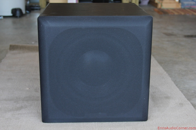
When I received the F12G Subwoofer from UPS and tried to carry it inside I nearly threw out my back. Like The Rolling Stones had Sympathy for the Devil (much to Don Mcleans chagrin), I immediately had sympathy for the deliveryman. At 90lbs shipping weight, this thing is a flat out hoss, which is certainly a hint at build quality.
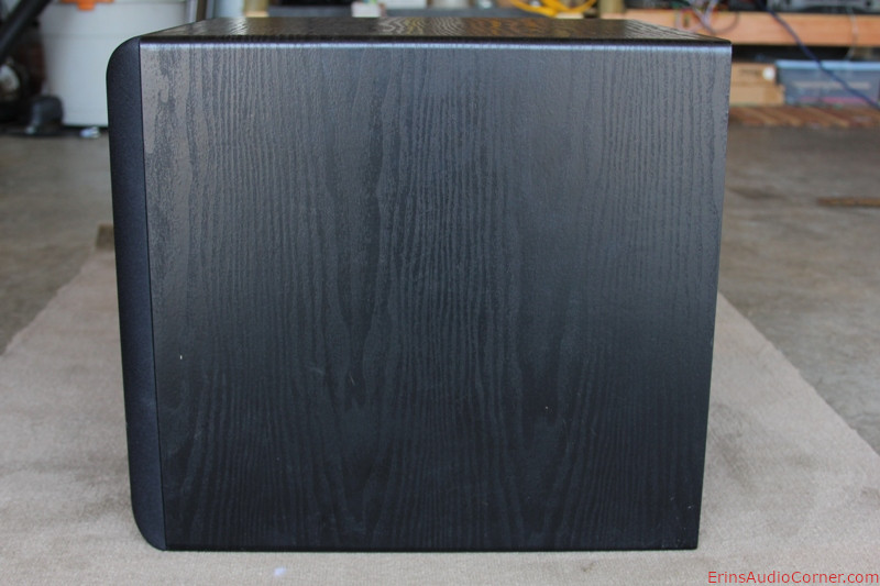
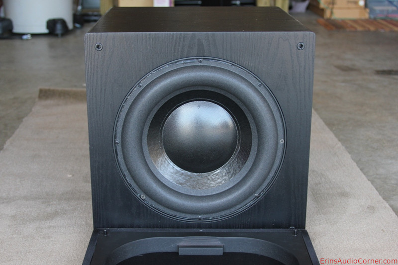
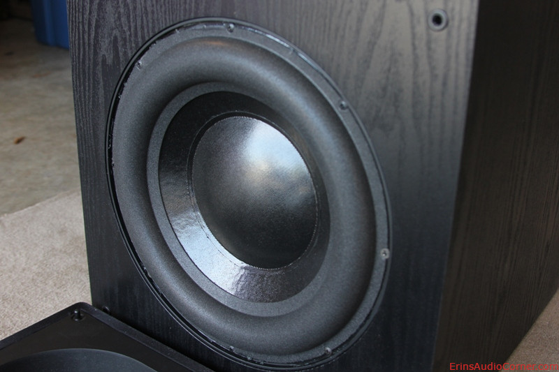
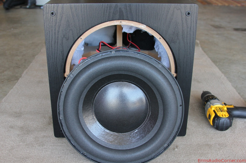
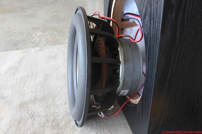
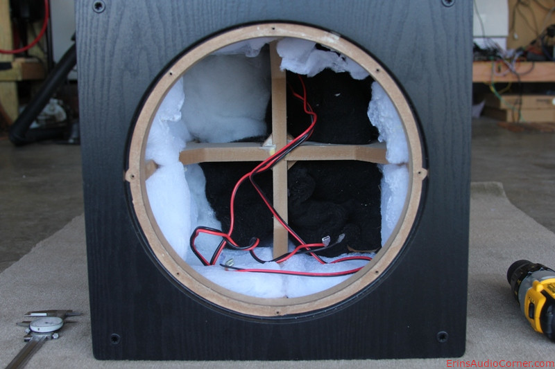
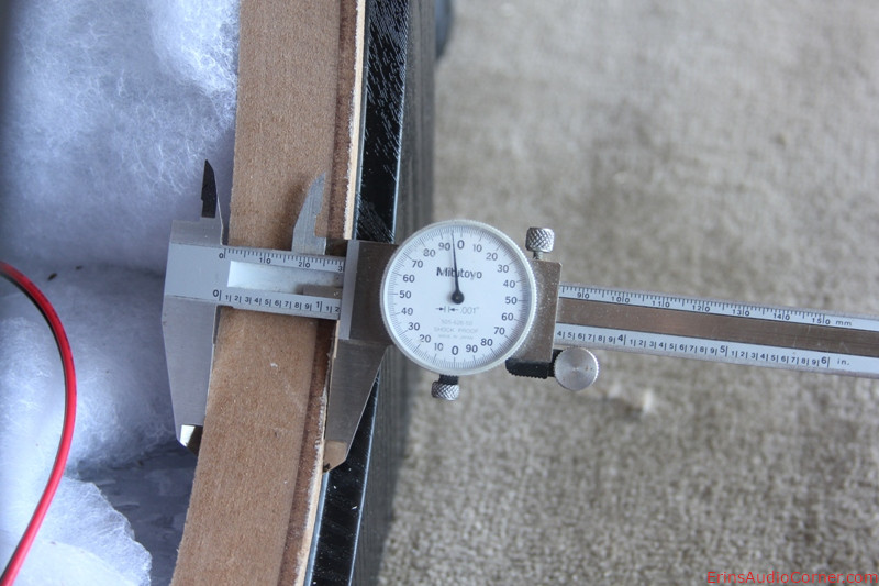
Removal of the subwoofer from the packaging revealed nothing eye grabbing. The sub I received came in the Black Oak finish*. While it doesn’t cosmetically exude top-flight class in the non-gloss finish, a peek inside the enclosure reveals that build quality is indeed top notch. As shown in the picture below, the front baffle is 1.5 inches thick. There is quite a bit of ¾ inch internal bracing and damping material used. Tapping on the box reveals a ‘dead’ sound. This will be reviewed later. Peeling back the damping material reveals some additional panels. I’m not sure what they are; they could be some form of constrained layer damping or some other form of damping. Having used numerous types of enclosures with bracing, I’m assuming these inner panels are a purposed material adding to the perceived ‘deadness’ of the enclosure itself.
Overall, while cosmetically not the most alluring subwoofer I’ve ever seen, the build quality is very high and it seems to me the efforts went where it’s most needed.
Editor’s comment: This subwoofer does come in a piano black finish for only $111 more.
Photos:
SW-12-04 Subwoofer Raw Driver Test Results:
Small Signal Analysis:
The following are the Thiele-Small parameters I measured using the Klippel LPM module.
| Electrical Parameters | |||
|---|---|---|---|
| Re | 3.52 | Ohm | electrical voice coil resistance at DC |
| fs | 20.8 | Hz | driver resonance frequency |
| Mechanical Parameters | |||
| (using added mass) | |||
| Mms | 135.212 g | mechanical mass of driver diaphragm assembly including air load and voice coil | |
| Mmd (Sd) | 123.809 g | mechanical mass of voice coil and diaphragm without air load | |
| Rms | 4.287 | kg/s | mechanical resistance of total-driver losses |
| Cms | 0.432 | mm/N | mechanical compliance of driver suspension |
| Kms | 2.32 | N/mm | mechanical stiffness of driver suspension |
| Bl | 12.365 N/A | force factor (Bl product) | |
| Loss factors | |||
| Qtp | 0.407 | total Q-factor considering all losses | |
| Qms | 4.128 | mechanical Q-factor of driver in free air considering Rms only | |
| Qes | 0.408 | electrical Q-factor of driver in free air considering Re only | |
| Qts | 0.371 | total Q-factor considering Re and Rms only | |
| Other Parameters | |||
| Vas | 133.2333 l | equivalent air volume of suspension | |
| Lm | 86.73 | dB | characteristic sound pressure level (SPL at 1m for 1W @ Re) |
| Lnom | 87.28 | dB | nominal sensitivity (SPL at 1m for 1W @ Zn) |
| Sd | 466.98 | cm² | diaphragm area |
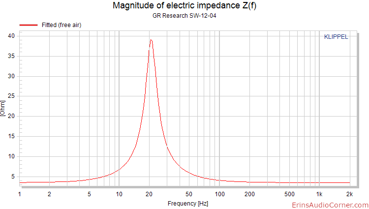
As you can see above, the Fs is low at 20.8 Hz. Qts and Vas ultimately net you a Qtc (in-box Qt) of 0.70 in an enclosure size of 1 cubic foot (not accounting for displacements of driver and bracing). That’s pretty respectable on its own. Decreasing enclosure size allows a bit more output in the 80hz region, however, that results in a loss of lower end output. This is where the amplifier’s damping adjustment options will help; you can smooth out the impedance bump caused by an undersized enclosure (often noted as box resonance) and extend the low end. This information is covered in further detail in the subsequent posts.
Large Signal Analysis:
The following is an inside peek in to the inner workings of a speaker driver. The Klippel LSI module is used to provide Linear One-Way Xmax: maximal excursion within some distortion threshold. In the case of subwoofers, the distortion threshold is 20% total harmonic distortion (THD) which is becoming the standard for acceptable subwoofer distortion thresholds¹. The data below provide engineers the ability to better understand how their product is performing in order to make adjustments to the design and improve performance and/or maximize the cost to performance ratio. It is worth mentioning that no driver is perfect and while some curves may look great, I’ve found the real engineers are making compromises where it makes sense.
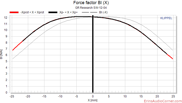
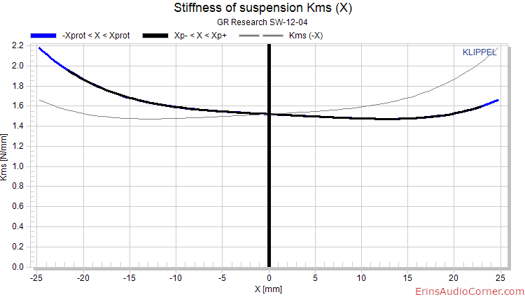
Linear excursion is typically comprised of three main aspects: 1) motor force over excursion (Bl(x)), 2) suspension over excursion (Km(x)), and 3) inductance over excursion (Le(x)). These parameters play in to the previously mentioned 20% THD threshold. The least of which is used to determine the driver’s linear performance for specification purposes.
The motor force, below, is given over excursion (driver voice coil in through coil out). What is shown is the force of the motor has a slight tilt to the curve illustrating approximately a 1.5mm coil inward offset.
Lastly, we consider the effect of inductance on the driver’s performance. Below are the results of both the inductance due to excursion (Le(x)) and inductance over current (Le(i)).. As the driver moves, the coil does, too. When current flows through the voice coil, there is a resistance to that flow of current known as inductance. As a driver moves forward and backward, the current in the coil changes. As the coil is closer to the magnet the magnetic field is higher than when the coil is ‘out’ and away from the magnet. So, you can imagine as the coil moves inward toward the magnet the inductance (or resistance to current) increases and as the coil moves out the inductance decreases. This results in a non-linear inductance performance. This is not desired. So, many manufacturers will put a shorting ring on the motor assembly (placement varies from design to design) in an attempt to cancel the magnetic flux as the coil enters the motor area where inductance is typically high. You can find good info and probably a much better explanation than I’ve given via Google if you wish.
Below is the result of the inductance as the driver moves through its excursion and vs current.
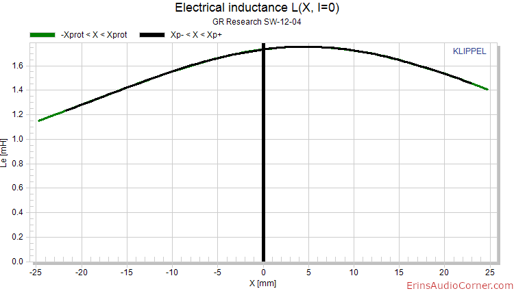
What you see in the Le(x) graph is a forward offset of the shorting ring by about 7mm.
So, Bl(x), Kms(x), and Le(x) have been provided. The following values associated with each parameter comprise the components’ limiting factor in one-way excursion:
| Displacement Limits | |||
|---|---|---|---|
| X Bl @ Bl min=70% | 17.8 | mm | Displacement limit due to force factor variation |
| X C @ C min=50% | >21.7 | mm | Displacement limit due to compliance variation |
| X L @ Z max=17 % | 18.9 | mm | Displacement limit due to inductance variation |
| X d @ d2=10% | 52.8 | mm | Displacement limit due to IM distortion (Doppler) |
From the above, using the prescribed Bl, Cms, and Zmax (Le(x)) values for linear excursion limits, the driver’s linear Xmax measures at 17.8mm, limited by Bl. That’s quite impressive.
Note: Where “>” is given, this simply means the data was not resolved. This is typically because the driver needs to stressed further. Most of the time this isn’t a problem but in some cases, it’s not necessary. As you see above, Bl and Le both resolved and either of them would be a limiting factor the linear excursion of this driver so I saw no need in further pushing this driver at the risk of permanent damage.
Footnotes: ¹ Patrick Turnmire of Red Rock Acoustics.
Frequency Response and associated Harmonic Distortion:
All Frequency Response, Harmonic Distortion and Cummulative Decary Spectrum (CSD, aka: “waterfall”) plots generated using Klippel’s TRF module.
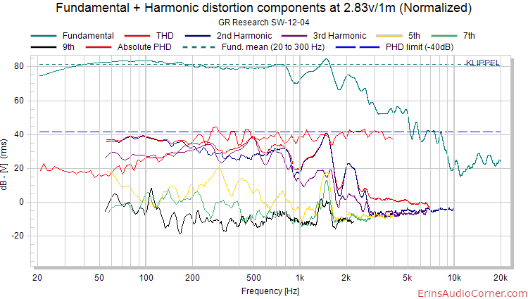
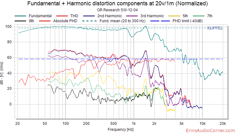
The following is a measurement of the SW-12-04 driver in the nearfield with SPL normalized to the 1 meter position. I measured the driver with an input of 2.83v and then with 20v input to illustrate how the distortion changes with higher output.
Raw Subwoofer Drive Unit Conclusion:
On its own, this driver performs really well. The low Fs of 20.8Hz, reasonable enclosure size requirements, good linearity, and low distortion with nearly 18mm one-way linear excursion all are attributes that make this a great value at its current MSRP of $179. I honestly would have no issue at all recommending it. Getting down to brass tacks, what this means is with the F12G Subwoofer, you know you have a great starting point with the SW-12-04 driver.
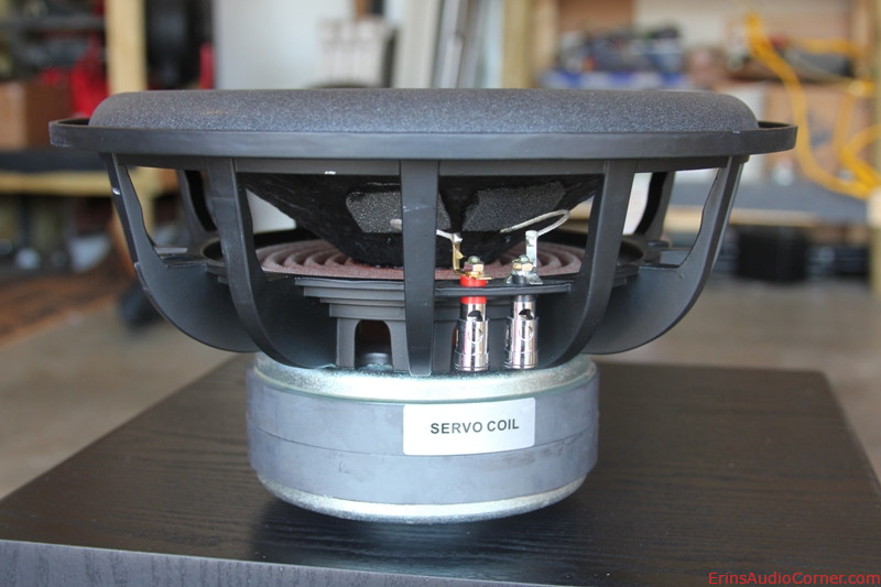
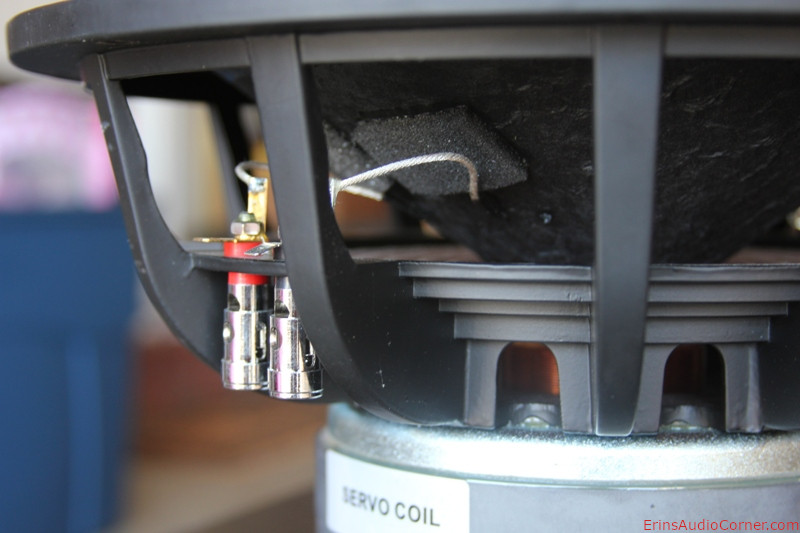
One thing that is a nice added touch is the felt material on the underside of the cone (shown in the pictures above). This is to minimize any audible tinsel lead slap on the cone. And I can say without a doubt, as I was testing this woofer to very high excursion levels (likely higher than anyone would actually achieve in real use), I never once heard any mechanical noise from the woofer driver.
Overall, the Harmonic Distortion components at 2.83v/1m are really low. The red PHD line is a representation of perceived harmonic distortion. You’ll note this is very, very low. With 20v input, putting the mean SPL from 20 to 300hz at about 98dB, THD climbs to about 3% THD at 60hz. However, this is mostly comprised of 2nd order distortion while 3rd order distortion is below 1.5%. Whether or not this is an audible factor seems to be of hot debate. The key here is the relationship between 2nd and 3rd order and that they’re well separated, indicating no serious flaws in the driver.
F12G Subwoofer Testing
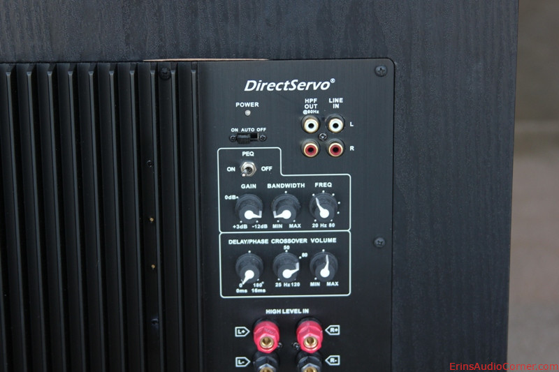
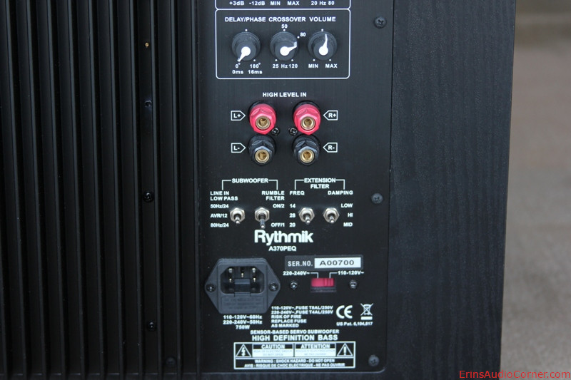
Thanks to its patented Direct Servo System, the F12G has numerous settings which allow the end user to tailor the sound to their own tastes or to blend better in their own setup. These settings can be found in detail on Rythmik’s site here. In a nutshell, however, you are able to choose how low you want the response to extend and how the low end response will be shaped, parametric EQ capability, and a “rumble filter”. I find these features very useful. However, simply knowing they are available isn’t quite enough. I am a visual learner so I wanted to share the measurements I obtained. Here are close ups of the amplifier’s settings:
Note:
- All the following tests were done with the amplifier’s crossover set wide open to 120hz/12dB.
- I did not test the crossover settings as crossovers are a well understood idea.
Low Frequency Extension and Damping (Q) adjustments:
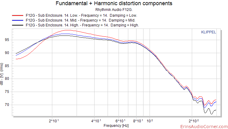
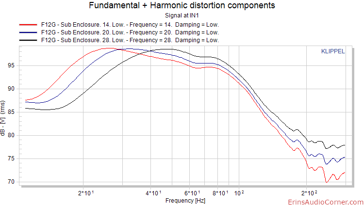
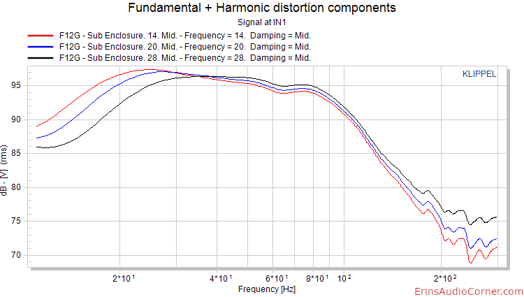
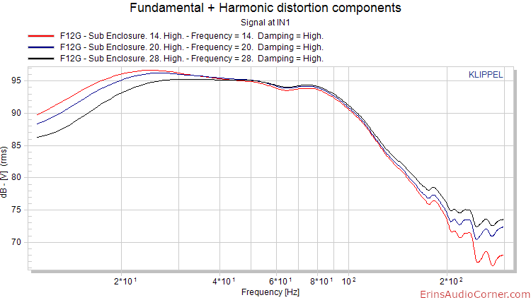
As shown above, you have (3) frequencies you can choose from: 14hz, 20hz, and 28hz. You also are able to choose from (3) different damping (Q) methods: low, mid, or high.
First, the damping switches. I set the extension frequency to 14hz and measured the response as I adjusted the Q from low, to mid, and to high. Here are the comparison results:
Next, I fixed the Q and altered between the (3) extension frequencies:
Parametric EQ:
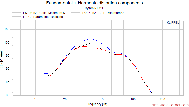
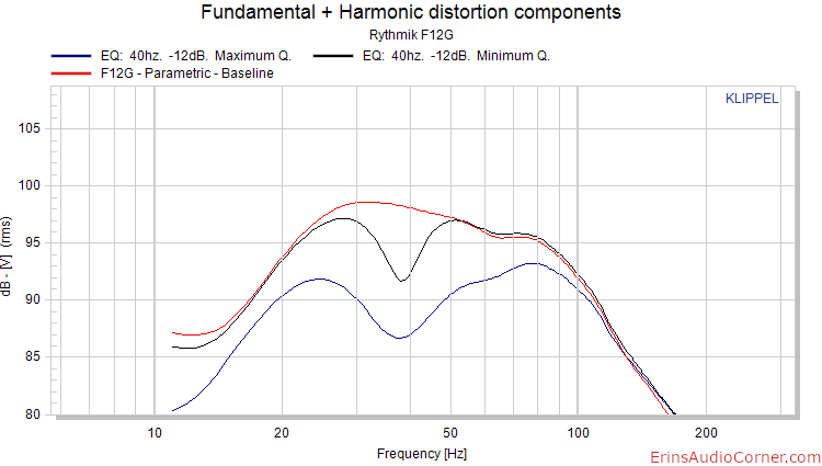
Another feature of the F12G is the amplifier’s parametric EQ. This feature is very useful to help adjust for the in-room response (ie: to tame a modal issue). The user is allowed to set the center frequency anywhere between 20hz to 80hz and an associated bandwidth. The bandwidth, or Q, dictates how wide or narrow the cut is. “Minimum” would be a narrow adjustment and “maximum” would be a very wide adjustment. The level of cut or boost is between -12dB to +3dB. Below are some examples of the various settings, compared to a ‘baseline’ frequency response to illustrate the adjustments’ effect.
+3dB Setting:
-12dB Setting:
Rumble Filter:
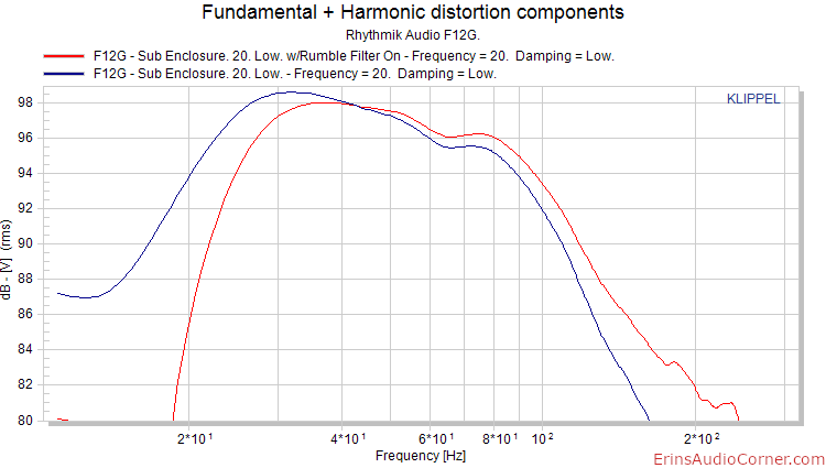
The F12G also comes with a rumble filter switch which helps to limit cone excursion if so desired. The picture below compares the response with a Mid Q, extension frequency at 20hz setting and filter on vs filter off.
Phase Adjustments:
Please see the below “In-Room Use” section for discussion on this feature.
Enclosure Resonance:
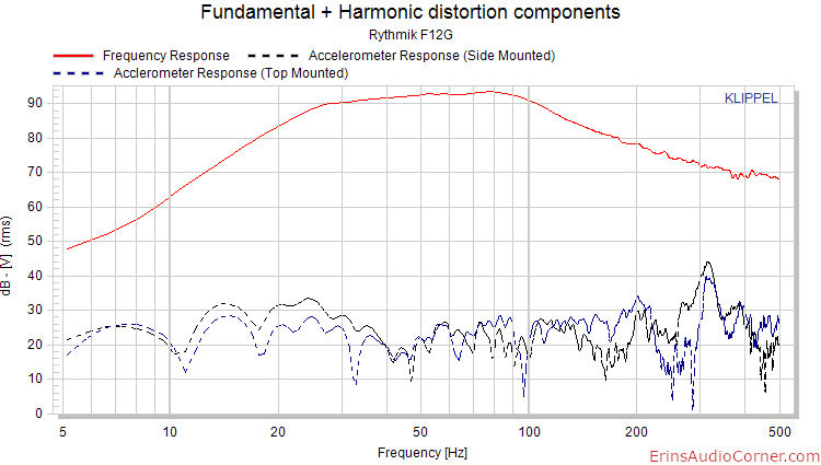
One test I like to see on loudspeakers and subwoofers is an accelerometer test. So, I wanted to present that here.
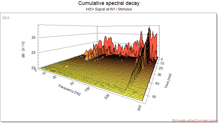
I measured the subwoofer’s response and normalized the SPL to 1m, giving about 92dB at 1m (referencing 50hz) using the measurement mic. The dashed lines represent the accelerometer response with the accelerometer placed at the side and then at the top of the enclosure. Comparing the two indicates a modal ringing around 310hz which is also verified by the CSD plot. Though, comparing to the frequency response of the subwoofer, there is no indication in this showing up. Furthermore, phase measurements don’t indicate a strong correlation between measured acoustic response vs structural response. So, while there is modal ringing measured, there’s no real indication this will be an audible detriment.
Note: I lost my calibration sheet for my accelerometer so the level at which the accelerometer results are given below are not absolute.
In-Room Use
I truly believe the most important factor in a great sounding system is smooth response. That’s pretty much a de facto standard. However, the next important item on my list is good, clean bass response. When bass is bloated and fat, plagued by improper phase alignment and modal issues, everything above it gets covered up. If you strive for detail and articulation in music or theater, you have to focus on the low end response and working to get it to sync well with the rest of your system in time and amplitude. This is why I was very happy to see the plethora of settings available on the F12G. I’ve covered most of these settings in the post above but it is worth looking at the real world application of a certain few. Below I have illustrated the Phase Delay setting as well as practical use of the Parametric EQ.
To perform these tests, I placed my test microphone approximately 2 meters from the speakers. The sub was placed on the floor between my pair of Kef Q100 bookshelf speakers and the volume was set to a typical listening level at 10pm.
Phase Delay:
Most subwoofers have a polarity switch that will reverse the signal so it can be better aligned with your speakers. This is not a trivial topic and much goes in to getting this dialed in just right. When you factor in the effect of the environment, typically due to placement, it becomes even harder to properly align the wavefront of the subwoofer to that of the other speakers in the room. While the 0/180 degree polarity switch on most amps helps somewhat, it leaves a wide range of potentially better fitting phase adjustments on the table. The F12G subwoofer picks up the slack where most other subwoofers leave off. The F12G permits the user the ability to fine tune the phase of the subwoofer so it can be closely matched to your other speakers. You can set the phase as 0 or 180, of course. However, the key feature here is you can also set the phase to any number between these two points. If you want to adjust the phase angle so it is 22 degrees, you can. Every system is different, so time and care should be taken to determine where this dial should be placed for your own system. As an example, I have highlighted the measured difference at 0, 90, and 180 degrees.
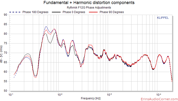
As you can see, each setting results in a different measured response. One might look at the 180 degree result and say it’s the most “in phase” with my Q100’s because it has the most amplitude. However, one thing to keep in mind is the fact there are always tradeoffs in home audio. In this case, I’d say the 90 degree measurement may be better because it still has close to the same amplitude as the 180 degree measurement. However, it doesn’t have the bump at approximately 56hz like 180 degrees does. This may be a way to get the best of both worlds: modal control and phase alignment. Of course, as I said above, every room is different and since bass is so dominated by the room the listener will have to decide what works best in their room. Who knows, there may be a phase angle between the (3) I’ve displayed that provides a smoother response.
Parametric Equalizer:
As I noted above, there’s an apparent modal issue at 56hz. The only real way to know for sure is to measure at different spots in the room, and perform decay (waterfall) measurements. Compare these to your frequency response and you’ll get a good idea of what’s a modal issue and what is not. Also, be careful not to confuse a peak in response with modal ringing in the room simply because of a peak. A dip in response can often fool you in to focusing on the peak next to it, rather than realizing the null itself is the real problem. (side note: it’s not wise to try to boost a null with EQ as often this is a cancellation that cannot be corrected via EQ)
Since I had frequency response measurements already, I performed decay analysis and found 56hz is indeed a lingering note in my room.
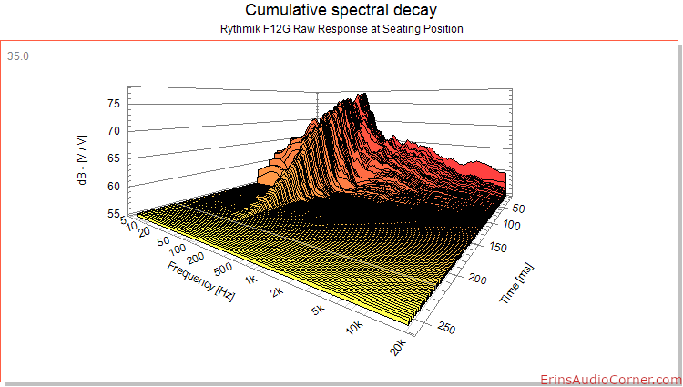
Since the modal issue has been verified, let’s use the amplifier’s built in parametric EQ to see if we can knock this down a bit and clean up the low end response.
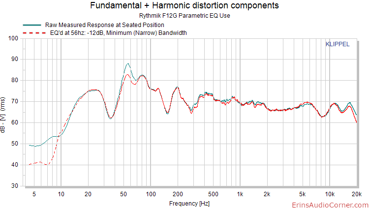
As you can see from the above, the center frequency was placed at approximately 56hz, a narrow Q was set, and the level of EQ applied was -12dB. What does the decay look like now?
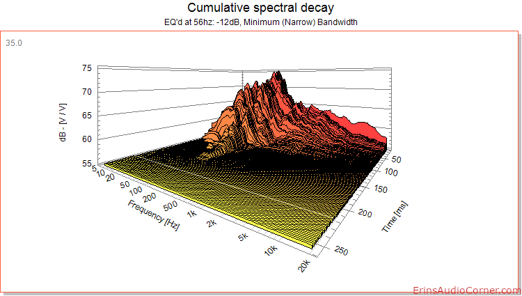
The ringing was decreased by roughly 50ms which helped to clear up the bloat occurring in the low frequency response.
When used properly, this kind of feature can do a lot to improve the clarity of your sound system.
Wrap-Up/Final thoughts
- Low distortion subwoofer driver with nearly 18mm one-way linear excursion!
- Sturdy and very robustly built enclosure that shows no legitimate signs of audible panel ringing
- Excellent features allowing the user to tailor the response to his room and tastes and achieve response below 20hz if so desired
- Low frequency extension settings
- Damping of low frequency extension
- Low pass filter options
- Parametric EQ (a very nice added bonus)
- Phase adjustment is an absolute treat
All in all, a very solid product with focus on not only quality but, most importantly, providing the user with the ability to tailor the sound to what works best for them. Given this, I have no problem recommending this to someone looking for an all-in-one subwoofer solution for their home.
End
If you like what you see here and want to help me keep it going, there’s a Paypal Contribute button at the bottom of each page. Just provide what you can. Every little bit is truly appreciated.
You can also join my Facebook and YouTube pages via the links at the bottom of the page if you’d like to follow along with updates.
Thanks!

