Up for test is a Seas W18NX-001. This is another driver that will be party of Jerry Niebur’s Midwoofer Subjective Shootout next month.
As always, please see my Test Setup and Methods page regarding test criterion.
Let’s get to the data and analysis…
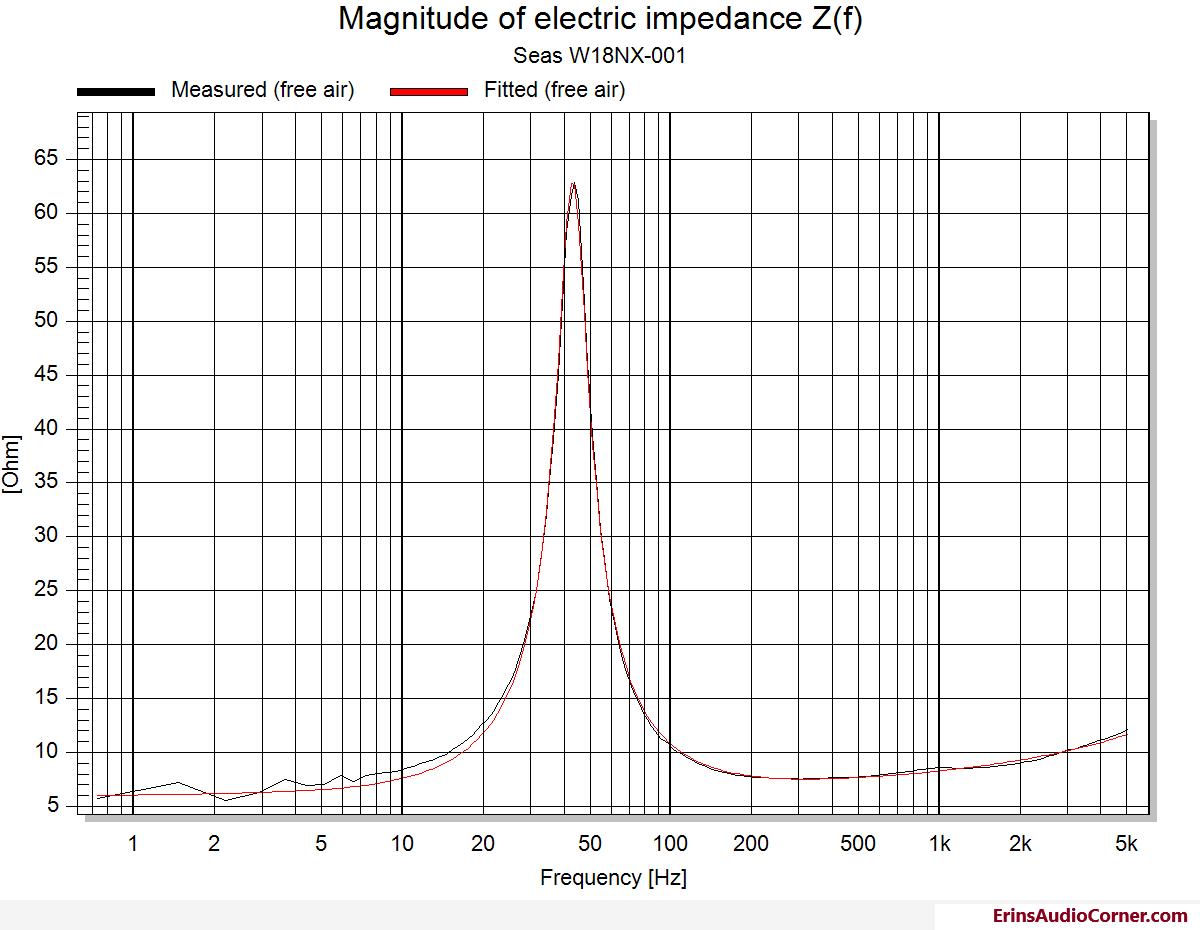
Theile-Small Parameters & Impedance
| Electrical Parameters | |||
|---|---|---|---|
| Re | 5.79 | Ohm | electrical voice coil resistance at DC |
| Krm | 0.1518 | Ohm | WRIGHT inductance model |
| Erm | 0.31 | WRIGHT inductance model | |
| Kxm | 0.0087 | Ohm | WRIGHT inductance model |
| Exm | 0.64 | WRIGHT inductance model | |
| Cmes | 247 | µF | electrical capacitance representing moving mass |
| Lces | 55.06 | mH | electrical inductance representing driver compliance |
| Res | 56.6 | Ohm | resistance due to mechanical losses |
| fs | 43.2 | Hz | driver resonance frequency |
| f ct | 55.3 | Hz | driver resonance frequency in enclosure |
| Mechanical Parameters | |||
| (using test encl.) | |||
| Mms | 15.657 | g | mechanical mass of driver diaphragm assembly including air load and voice coil |
| Mmd (Sd) | 13.634 | g | mechanical mass of voice coil and diaphragm without air load |
| Rms | 1.121 | kg/s | mechanical resistance of total-driver losses |
| Cms | 0.868 | mm/N | mechanical compliance of driver suspension |
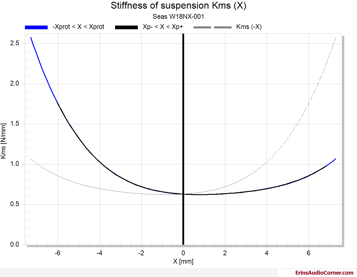
| Kms | 1.15 | N/mm | mechanical stiffness of driver suspension |
| Bl | 7.966 | N/A | force factor (Bl product) |
| Loss factors | |||
| Qtp | 0.399 | total Q-factor considering all losses | |
| Qms | 3.789 | mechanical Q-factor of driver in free air considering Rms only | |
| Qes | 0.388 | electrical Q-factor of driver in free air considering Re only | |
| Qts | 0.352 | total Q-factor considering Re and Rms only | |
| Other Parameters | |||
| Vas | 26.6853 | l | equivalent air volume of suspension |
| n0 | 0.533 | % | reference efficiency (2 pi-radiation using Re) |
| Lm | 89.46 | dB | characteristic sound pressure level (SPL at 1m for 1W @ Re) |
| Lnom | Zn missing | dB | nominal sensitivity (SPL at 1m for 1W @ Zn) |
| rmse Z | 4.53 | % | root-mean-square fitting error of driver impedance Z(f) |
| Sd | 147.41 | cm² | diaphragm area |
Klippel Large Signal Analysis
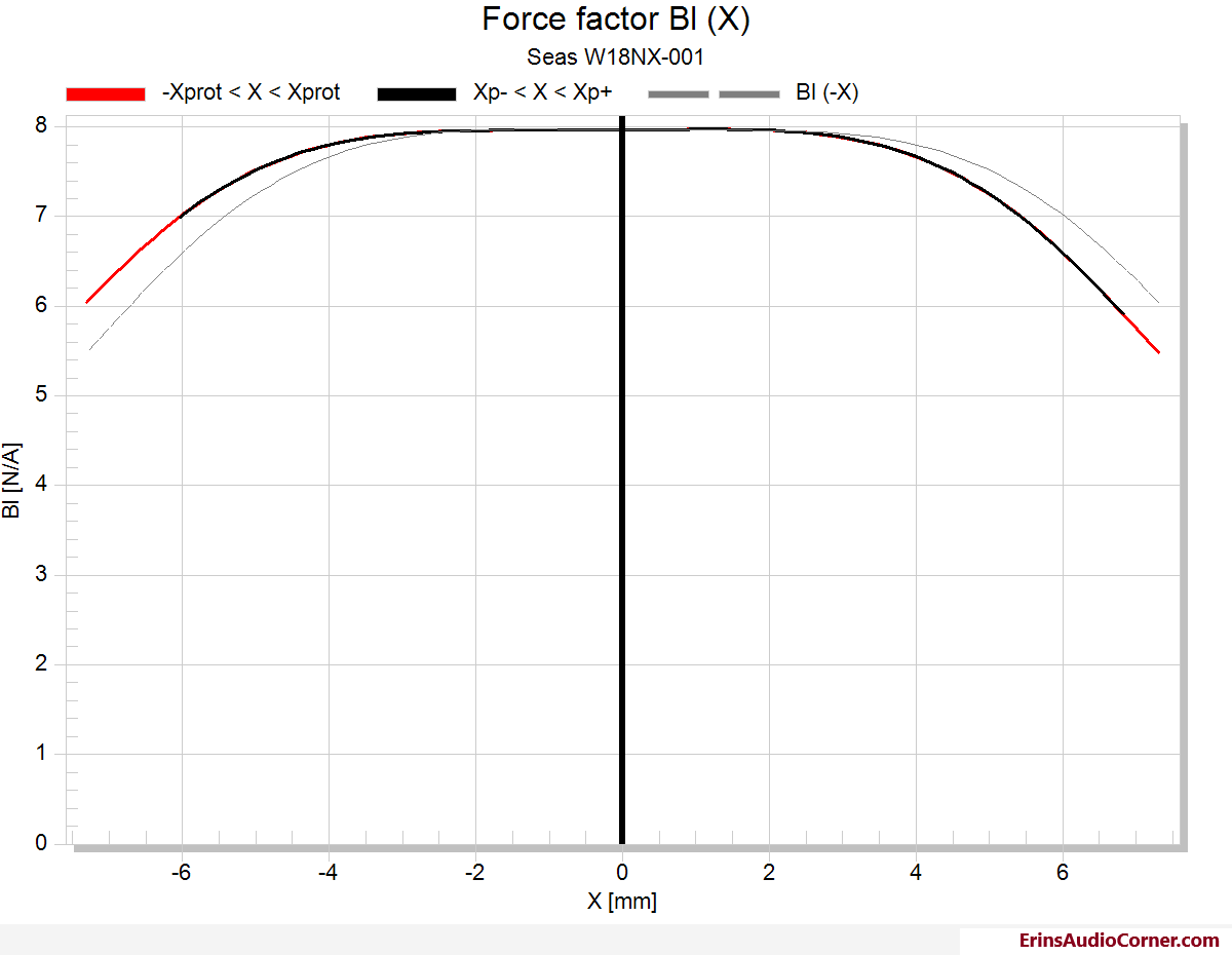
Fairly broad Bl curve which shows a constant motor force with xmin/xmax (in/out). Coil out offset at rest which trends toward the center of the magnetic gap at xmech with only a 0.30 inset.
Coil out offset which increases from 0.8mm at rest to 1.6mm at xmech. As you’ll see below, this is what limits the linear excursion (10% THD) for this driver and as a result, Bl related excursion is not able to resolve.
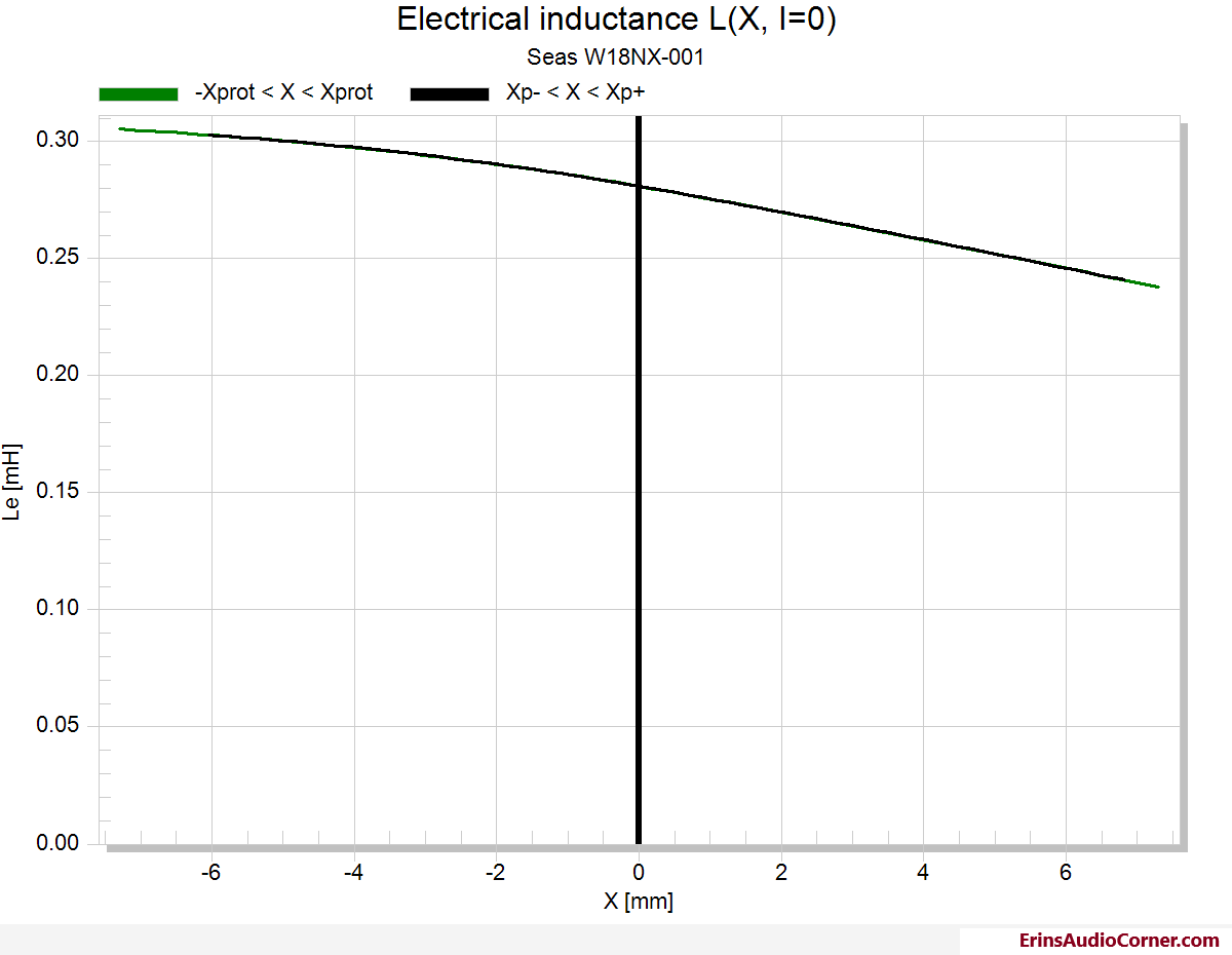
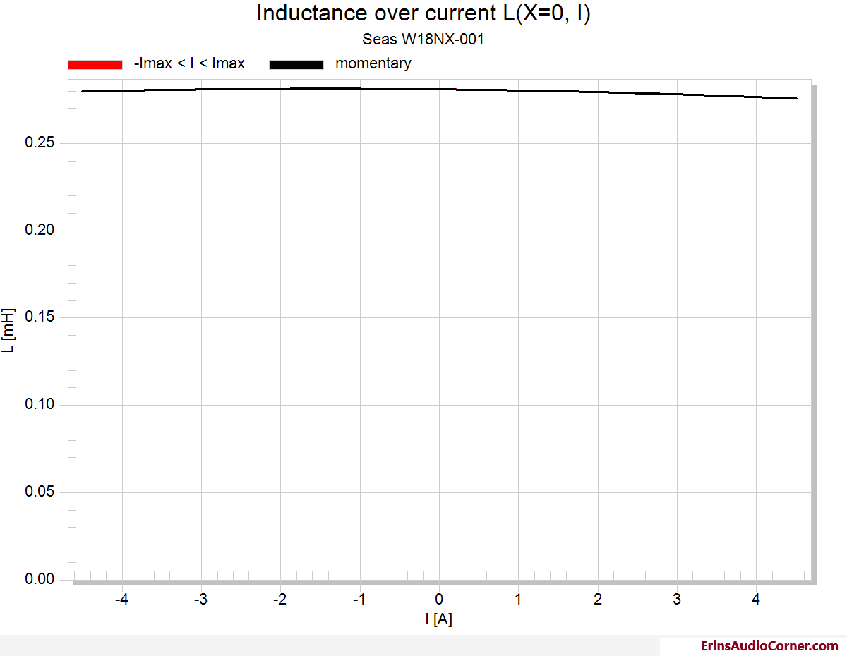
Low inductance over excursion shows a shorting ring was implemented to lower intermodulated distortion.
| Displacement Limits | thresholds can be changed in Processing property page | ||
|---|---|---|---|
| X Bl @ Bl min=82% | >6.0 | mm | Displacement limit due to force factor variation |
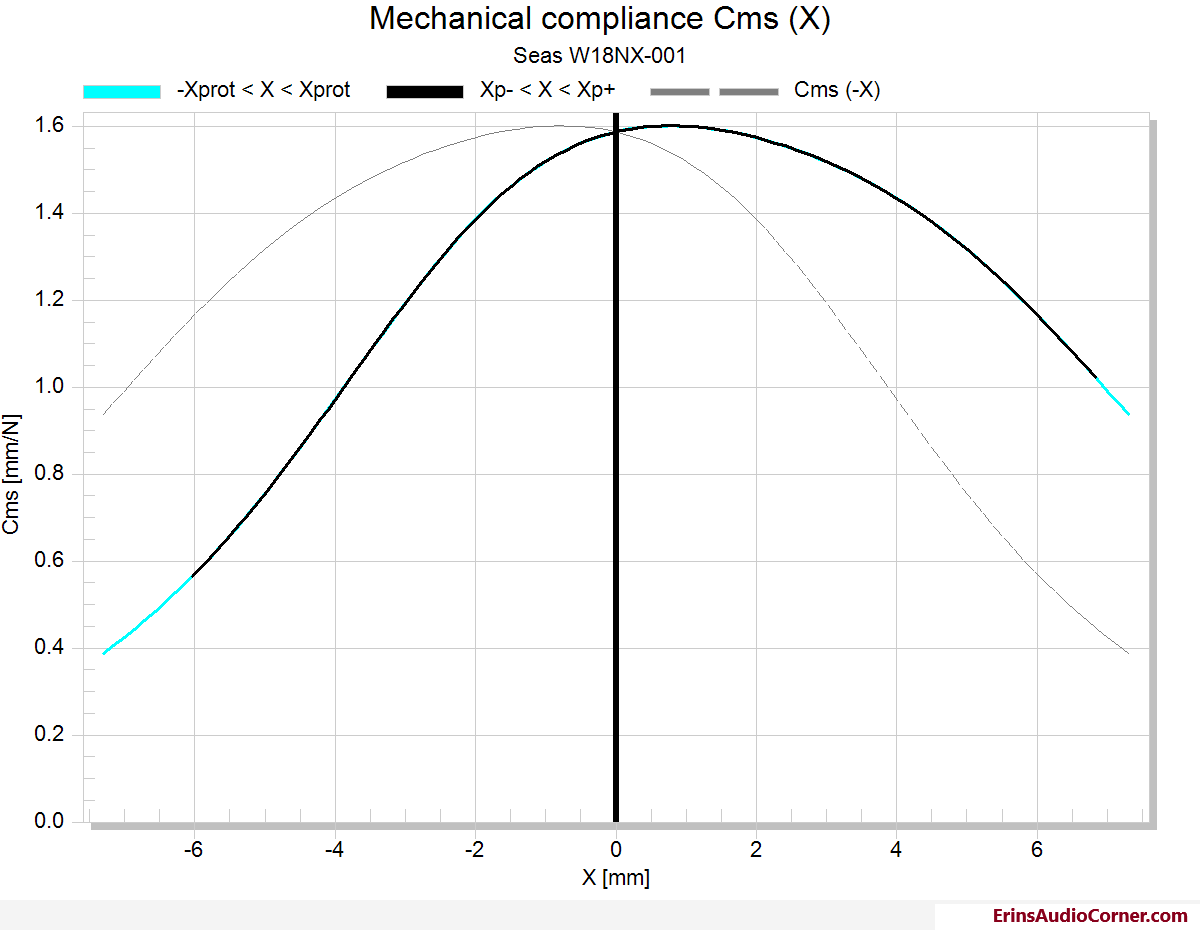
| X C @ C min=75% | 3 | mm | Displacement limit due to compliance variation |
| X L @ Z max=10 % | >6.0 | mm | Displacement limit due to inductance variation |
| X d @ d2=10% | 28.4 | mm | Displacement limit due to IM distortion (Doppler) |
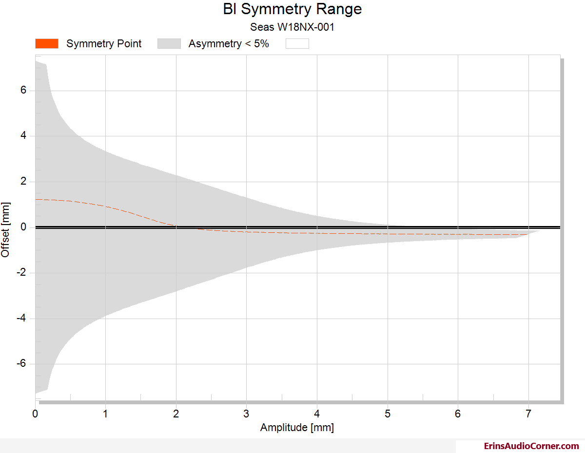
| Asymmetry (IEC 62458) | |||
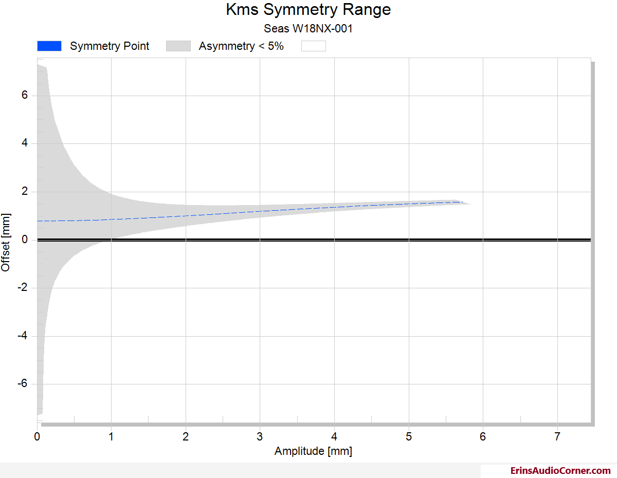
| Ak | 82.83 | % | Stiffness asymmetry Ak(Xpeak) |
| Xsym | -0.31 | mm | Symmetry point of Bl(x) at maximal excursion |
Unfortunately, the assymetry of suspension is the limiting factor here with a low 3 mm as the 10% THD contributing factor.
Frequency Response and Harmonic Distortion at 2.83v/1m
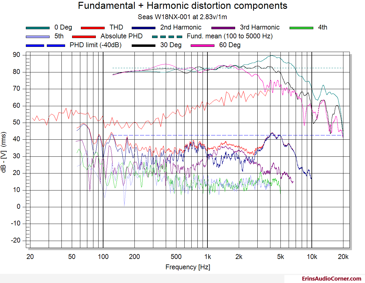
Ignoring the lower frequency non-linearity caused by the measurement conditions at the time: Good up until about 3khz in all measured axes. A potential mode at 4khz (as indicated by the same peak in response in all axes). Overall low distortion at this measurement distance/level to about 4khz where the THD breaks 1% (PHD level of -40dB).
3rd order distortion appears to be an issue at the 1-2khz range at this level. But, as you see below, when pushed harder, 2nd order takes over and 3rd order remains relatively low.
High Output Harmonic Distortion
Measurements taken in the nearfield to simulate 96dB @ 1m output.
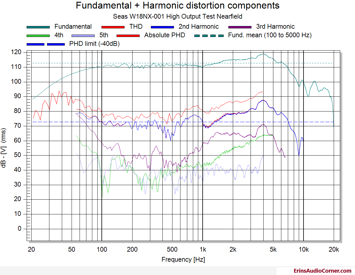
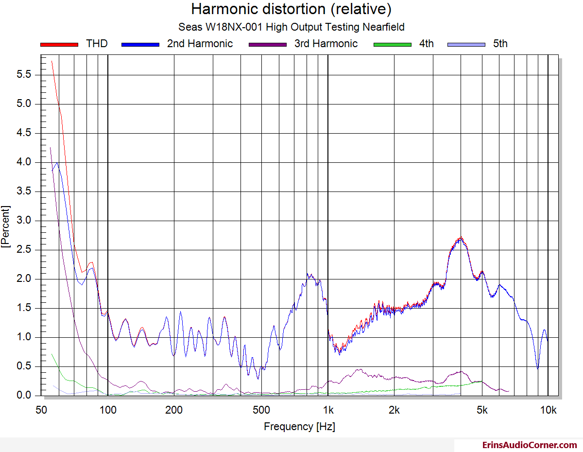
Very low 3rd order distortion from 100hz up to about 1khz where it increases slightly. Very slightly.
However, 2nd order distortion is the main culprit of distortion here and shows signs of concern centered about 900hz and 4khz; which would put the harmonic tones at about 1800hz and 8khz. Not that I can undoubtedly say these are problematic, paired with the fact the impedance data shows no signs of resonance here, I am betting this is cone breakup artifacts and would be mitigated by using these within 2-3khz low-pass. On the low end, 2nd order still dominates, however, 3rd order starts rapidly increasing above 80hz. At about 68hz, THD is above 3% and 3rd itself is above 3% at 60hz.
Thoughts
Back 5+ years ago this was a fine mid/woofer value. But by today’s standards I can’t reasonably recommend it. If used more like a traditional 6.5" midrange between, say, 100-2khz the distortion (linear and non-linear) effects wouldn’t be too bad. And at its current price (of this writing) at $139/each it’s not a bad value. But I can’t say that it’s a great value, either. I’d look around at something else to fit your needs.
End
If you like what you see here and want to help me keep it going, there’s a Paypal Contribute button at the bottom of each page. Just provide what you can. Every little bit is truly appreciated.
You can also join my Facebook and YouTube pages via the links at the bottom of the page if you’d like to follow along with updates.
Thanks!