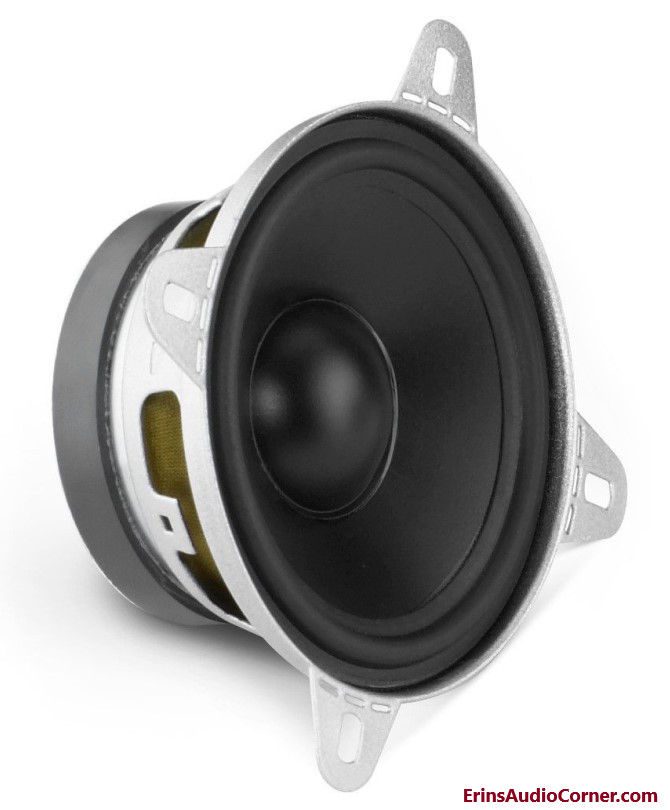
Up for test is a JL Audio C5-400cm midrange. I was interested in this driver as it seems to be of reasonable cost given the small form factor and mounting options in addition to the fact that it uses a Kurt Müller cone design, which is a well regarded cone manufacturer.
As shown in the pictures below, this driver comes with a mounting ring which allows it to be installed in a manner using the ring and covering grille (not shown). The alternative, shown in the above photo and provided link, is to use the driver with the mounting tabs. When I initially received this driver I removed the tabs for install purposes and therefore this particular test is done with the mounting ring in place. Keep this in mind when viewing the frequency response measurements.
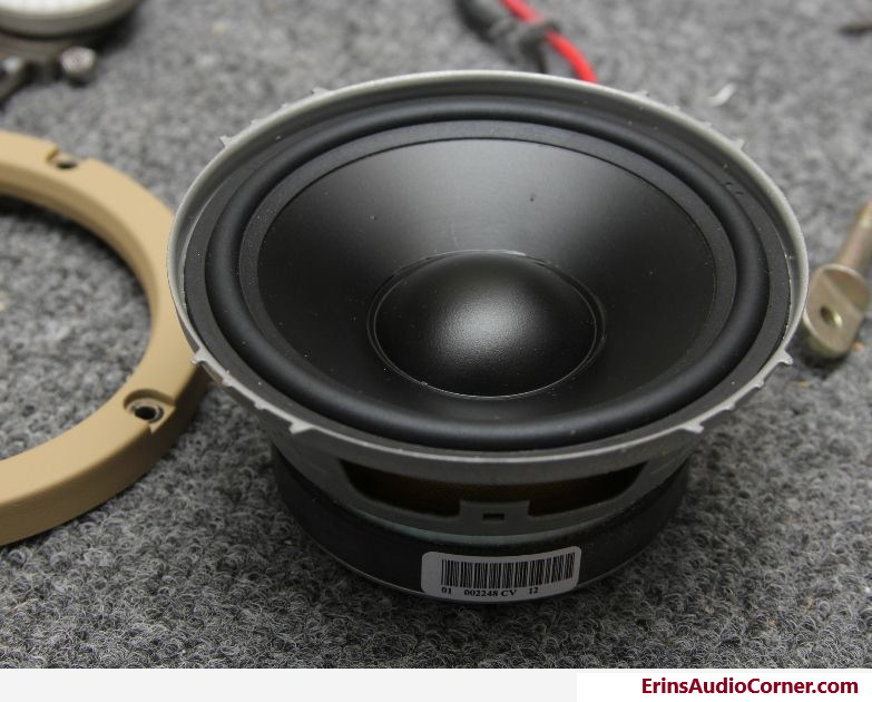
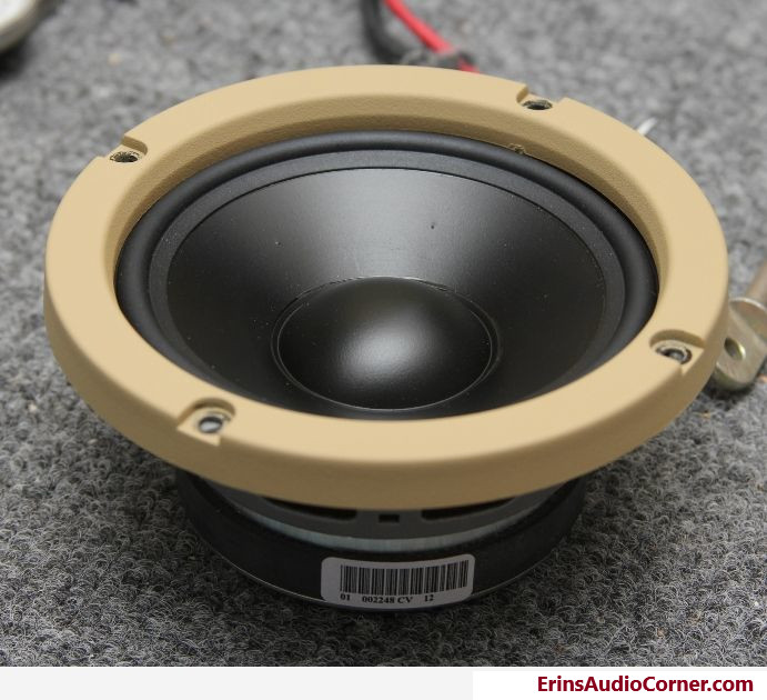
To illustrate the difference with the ring attached, I have shown the driver with and without the ring. Again, however, note that I have removed the tabs for my particular application.
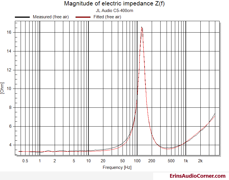
Thiele-Small Parameters and Impedance Measurement
| Electrical Parameters | |||
|---|---|---|---|
| Re | 3.32 | Ohm | electrical voice coil resistance at DC |
| Le | 0.168 | mH | frequency independent part of voice coil inductance |
| L2 | 0.237 | mH | para-inductance of voice coil |
| R2 | 2.21 | Ohm | electrical resistance due to eddy current losses |
| Cmes | 362 | µF | electrical capacitance representing moving mass |
| Lces | 4.55 | mH | electrical inductance representing driver compliance |
| Res | 13.23 | Ohm | resistance due to mechanical losses |
| fs | 124 | Hz | driver resonance frequency |
| Mechanical Parameters | |||
| (using test encl.) | |||
| Mms | 4.87 | g | mechanical mass of driver diaphragm assembly including air load and voice coil |
| Mmd (Sd) | 4.427 | g | mechanical mass of voice coil and diaphragm without air load |
| Rms | 1.017 | kg/s | mechanical resistance of total-driver losses |
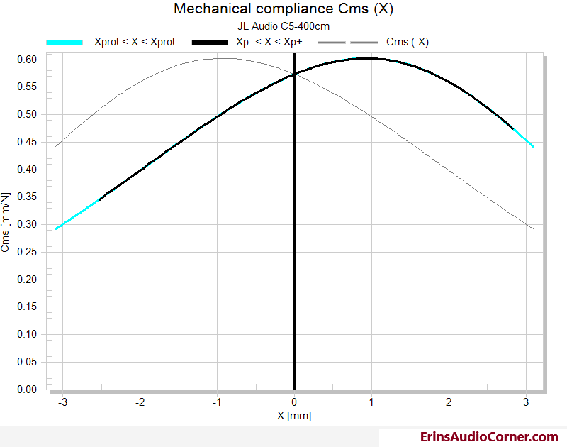
| Cms | 0.338 | mm/N | mechanical compliance of driver suspension |
| Kms | 2.96 | N/mm | mechanical stiffness of driver suspension |
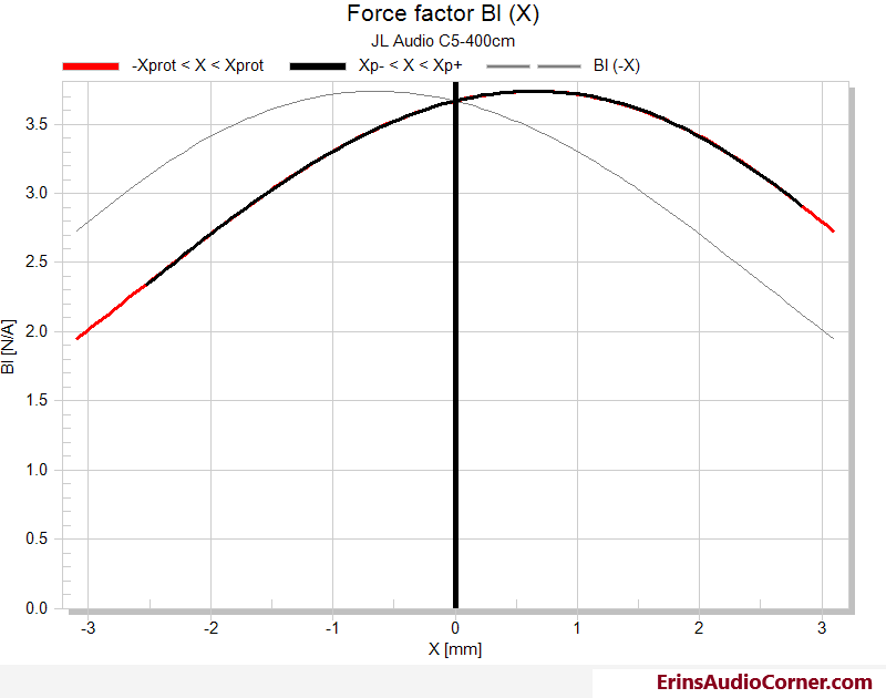
| Bl | 3.668 | N/A | force factor (Bl product) |
| Loss factors | |||
| Qtp | 0.751 | total Q-factor considering all losses | |
| Qms | 3.731 | mechanical Q-factor of driver in free air considering Rms only | |
| Qes | 0.935 | electrical Q-factor of driver in free air considering Re only | |
| Qts | 0.748 | total Q-factor considering Re and Rms only | |
| Other Parameters | |||
| Vas | 1.3742 | l | equivalent air volume of suspension |
| n0 | 0.269 | % | reference efficiency (2 pi-radiation using Re) |
| Lm | 86.5 | dB | characteristic sound pressure level (SPL at 1m for 1W @ Re) |
| Lnom | 87.32 | dB | nominal sensitivity (SPL at 1m for 1W @ Zn) |
| Sd | 53.59 | cm² | diaphragm area |
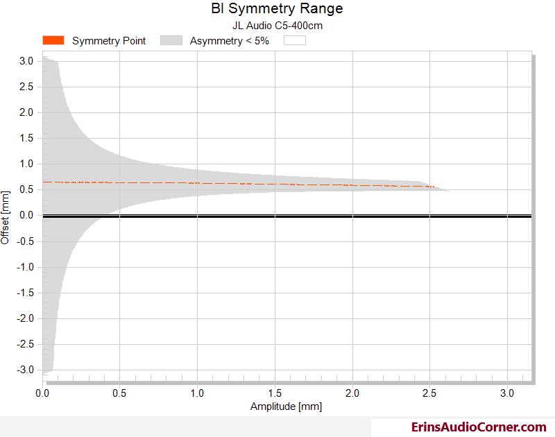
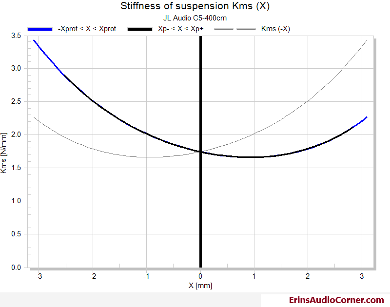
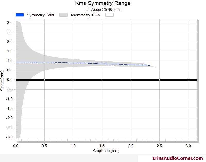
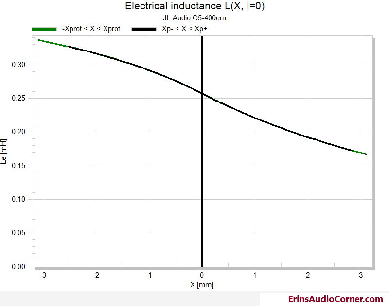
Large Signal Analysis with Klippel’s LSI Module
| Displacement Limits | |||
|---|---|---|---|
| X Bl @ Bl min=82% | 1.5 | mm | Displacement limit due to force factor variation |
| X C @ C min=75% | 1.7 | mm | Displacement limit due to compliance variation |
| X L @ Z max=10 % | 1.7 | mm | Displacement limit due to inductance variation |
| X d @ d2=10% | 9.5 | mm | Displacement limit due to IM distortion (Doppler) |
| Asymmetry (IEC 62458) | |||
| Ak | 40.93 | % | Stiffness asymmetry Ak(Xpeak) |
| Xsym | 0.58 | mm | Symmetry point of Bl(x) at maximal excursion |
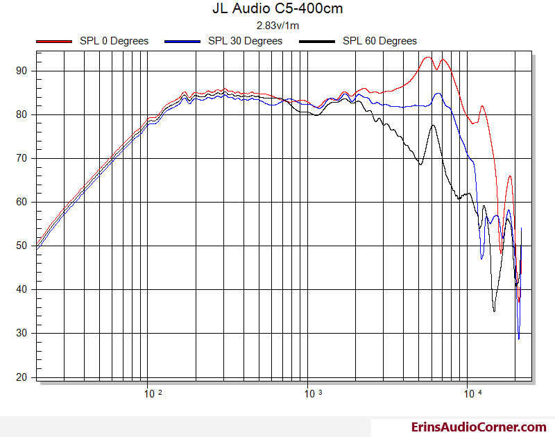
Frequency Response
The following measurement was done by merging nearfield and farfield results together at 500hz to yield a quasi-anechoic result.
Also, remember this driver was mounted to the baffle with the mounting ring attached. This will effect the higher frequency response but unfortunately I didn’t have a way to test without it. Please read the parting comments at the bottom for some more on this.
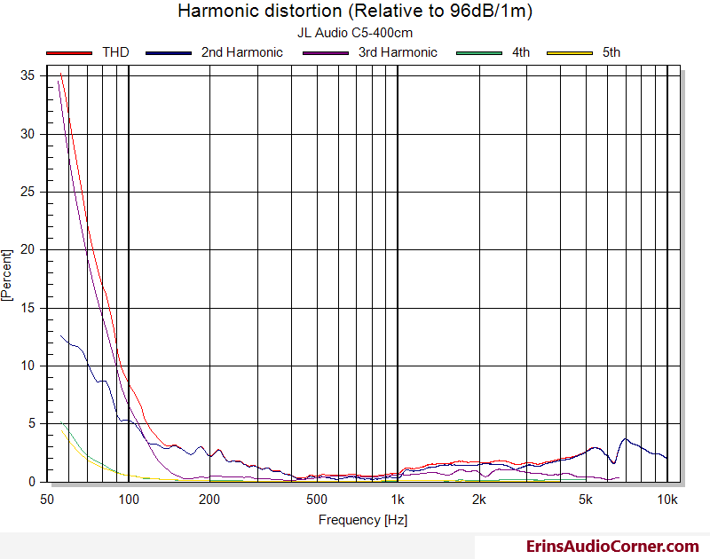
Harmonic Distortion
This test was performed in the nearfield at an SPL level equal to 96dB at 1 meter.
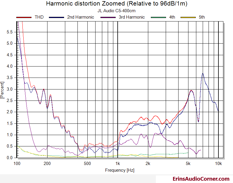
This is the same as above, just zoomed in for legibility.
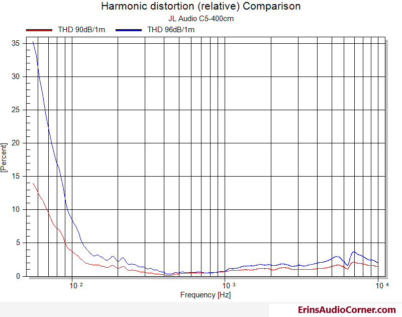
For those who may be curious how output levels drive the non-linear performance in terms of harmonic distortion, I have provided an example below. In Red is the THD measured at 90dB/1m. In Blue is the THD measured at 96dB/1m.
Thoughts
The measured sensitivity is about 84-85dB on average from 200Hz to 4kHz which is the band I would keep this driver in given the increased harmonic distortion below 200hz and the increased linear distortion (bumps in frequency response) above 4kHz. The breakup around 5-7kHz could very well be from the mounting ring; given the distance from the center of the cone to the outer edge it makes sense it would impact it around these frequencies. However, the fact that people would likely use the ring to install the driver makes it a worthwhile method to test and I’ll continue my evaluation with that mindset. So, having said that, the “breakup” is kept in check fairly well so with a steep low-pass filter placed around 4kHz or below the level of this breakup should be low enough to not significantly impact the overall response of the system.
At 30 degrees off-axis you can see the frequency response is fairly linear which indicates this may have been the targeted aiming for this speaker, given its use in car audio where midrange drivers may need to be placed in this manner so they don’t obtruct the driver’s view.
End
If you like what you see here and want to help me keep it going, there’s a Paypal Contribute button at the bottom of each page. Just provide what you can. Every little bit is truly appreciated.
You can also join my Facebook and YouTube pages via the links at the bottom of the page if you’d like to follow along with updates.
Thanks!