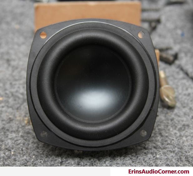
I’ve seen the Aurasound NS3 drivers discussed frequently as a great little driver to use in small spaces, with all sorts of potential uses.. So, naturally, I had to order a few to see for myself. The results are actually quite nice. Unfortunately, to get the excursion they do have, they give up a good deal of sensitivity as well.
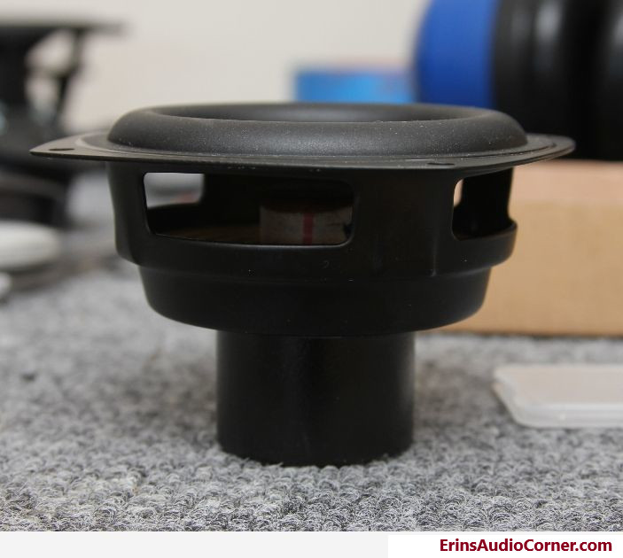
Note: I made sure to chamfer the backside of the baffle in order to let this driver breathe a bit more efficiently. I suggest others do the same or at least consider the implications if they do not.
Okay, Okay… On with the results…
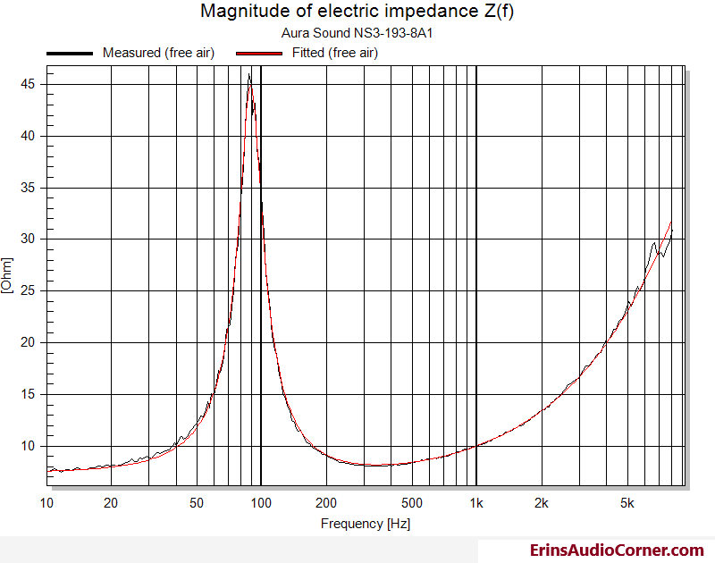
Thiele-Small Results
| Electrical Parameters | |||
|---|---|---|---|
| Re | 7.45 | Ohm | electrical voice coil resistance at DC |
| Krm | 0.0004 | Ohm | WRIGHT inductance model |
| Erm | 0.93 | WRIGHT inductance model | |
| Kxm | 0.0056 | Ohm | WRIGHT inductance model |
| Exm | 0.78 | WRIGHT inductance model | |
| Cmes | 197 | µF | electrical capacitance representing moving mass |
| Lces | 16.22 | mH | electrical inductance representing driver compliance |
| Res | 37.38 | Ohm | resistance due to mechanical losses |
| fs | 89 | Hz | driver resonance frequency |
| —————— | |||
| fm | 68.3 | Hz | resonance frequency of driver with additional mass |
| Mechanical Parameters | |||
| (using add. mass) | |||
| Mms | 4.01 | g | mechanical mass of driver diaphragm assembly including air load and voice coil |
| Mmd (Sd) | 3.818 | g | mechanical mass of voice coil and diaphragm without air load |
| Rms | 0.545 | kg/s | mechanical resistance of total-driver losses |
| Cms | 0.797 | mm/N | mechanical compliance of driver suspension |
| Kms | 1.26 | N/mm | mechanical stiffness of driver suspension |
| Bl | 4.513 | N/A | force factor (Bl product) |
| Loss factors | |||
| Qtp | 0.697 | total Q-factor considering all losses | |
| Qms | 4.118 | mechanical Q-factor of driver in free air considering Rms only | |
| Qes | 0.821 | electrical Q-factor of driver in free air considering Re only | |
| Qts | 0.684 | total Q-factor considering Re and Rms only | |
| Other Parameters | |||
| Vas | 1.0612 | l | equivalent air volume of suspension |
| n0 | 0.088 | % | reference efficiency (2 pi-radiation using Re) |
| Lm | 81.63 | dB | characteristic sound pressure level (SPL at 1m for 1W @ Re) |
| Lnom | 81.94 | dB | nominal sensitivity (SPL at 1m for 1W @ Zn) |
| Sd | 30.68 | cm² | diaphragm area |
Klippel Large Signal Identification (LSI) Results
Upon obtaining the small signal results above, I ran the Klippel LSI module to extract the ‘engineering data’ of motor and suspension characteristic curves and subsequent linear excursion values.
As with all my LSI testing, I ran the LSI module a couple times to see how varying the protection parameters altered the curve fit results. The results were always nearly the exact same. While I do this, I also am near the driver listening for deficiencies. During the last run, when the protection parameters were relaxed a bit more, I noticed a mechanical noise that sounded like the voice coil hitting the backplate, so I let off the gas a bit and proceeded with the test without issue. I note this because this tells me if you want to listen loud (and you very well may find you are doing so to compensate for the low sensitivity), you should listen for these noises or simply use a suitable high pass filter.
The below evidences a linear excursion (taken at 10% THD) of 3.5mm limited by the motor, while the suspension component of THD checks in at 4.4mm.
| Displacement Limits | thresholds can be changed in Processing property page | ||
|---|---|---|---|
| X Bl @ Bl min=82% | 3.5 | mm | Displacement limit due to force factor variation |
| X C @ C min=75% | 4.4 | mm | Displacement limit due to compliance variation |
| X L @ Z max=10 % | >4.5 | mm | Displacement limit due to inductance variation |
| X d @ d2=10% | 14.5 | mm | Displacement limit due to IM distortion (Doppler) |
| Asymmetry (IEC 62458) | |||
| Ak | -2.53 | % | Stiffness asymmetry Ak(Xpeak) |
| Xsym | -0.3 | mm | Symmetry point of Bl(x) at maximal excursion |
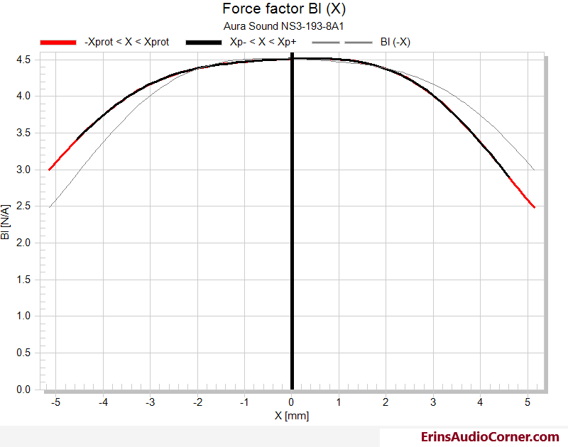
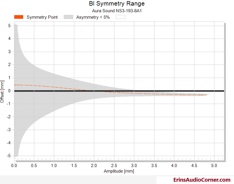
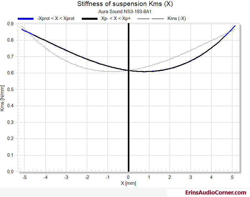
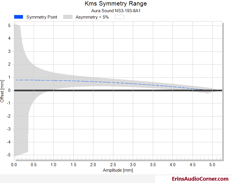
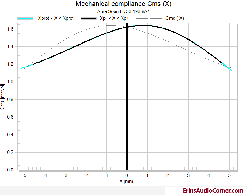
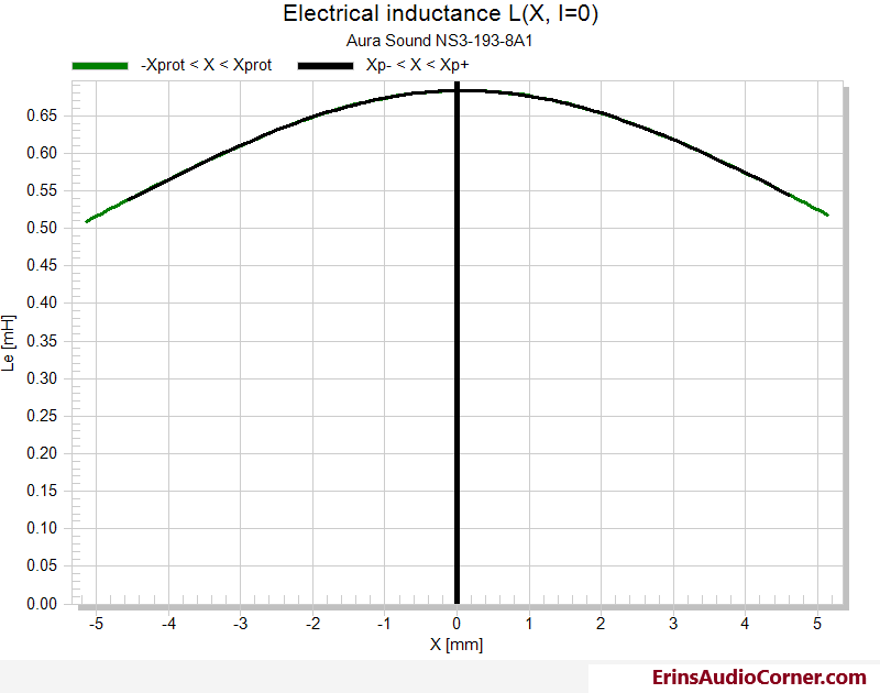
There’s a tilted offset in suspension here but doesn’t really seem to contribute much to the limitations of the driver, though, as it’s 2nd order dominated distortion on the low end near Fs where you’re likely already using a filter to limit excursion to some degree. The use of a shorting ring is evidenced by the symmetry in coil in/out excursion, which should help to limit higher frequency intermodulated distortion (distortion borne from a driver playing low and high frequency content at the same time.. ie: music). Overall, impressive results for a driver as small as this.
Frequency Response
The following on and off-axis curves were obtained by merging nearfield and farfield results together at approximately 450hz by use of the method described here.
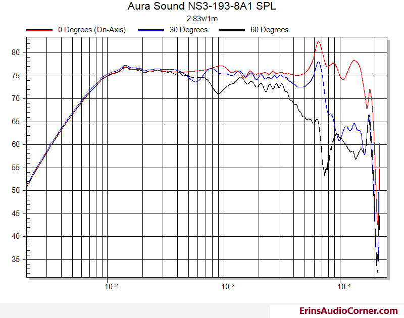
A very smooth on and off-axis response here with about +/1dB divergence in response on-axis from 200hz to 5000hz and f3 extension in to the low 70hz region. A notch filter to tame the breakup at approximately 6.5khz (as evidenced by the off-axis response) should allow excellent on-axis response out to at least 10khz. Though, as with any wideband/fullrange driver used past the point of beaming where the wavelength » cone diameter, there is a large difference in sound level in the various measurement/listening axes as you increase in frequency. For example, each curve follows the same trend and relative SPL until about 3khz where the response diverges. At 10khz the difference from 0 degrees to 60 degrees is approximately 15dB. Keep this in mind if you are concerned with articulation in the top octaves. In other words, when using drivers like this in “fullrange” operating (without mating to a tweeter), you’ll likely want to keep them on-axis (in my humble opinion).
Harmonic Distortion
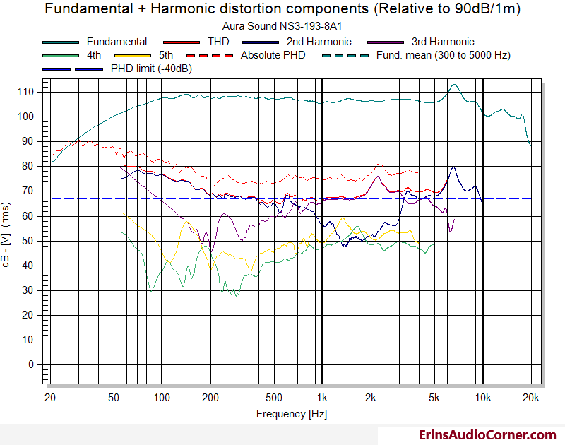
Below I have provided data from 2 different sets of HD testing: 90dB at 1 meter and 96dB at 1 meter. This is to provide you with an idea of how the output levels alter the distortion components. Each test was done in the nearfield at a level that approximates both of the values given before. 96dB at 1 meter from one driver is pretty loud.
90dB/1m:
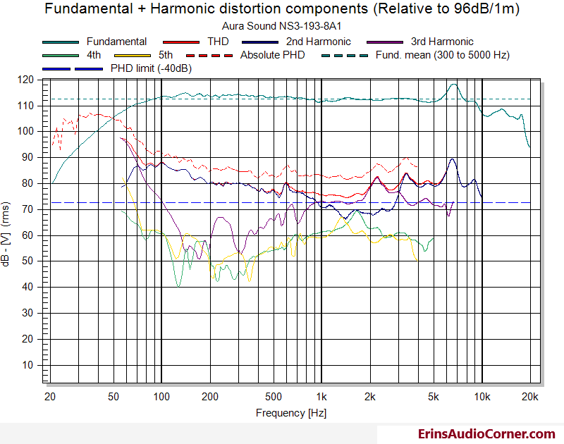
96dB/1m:
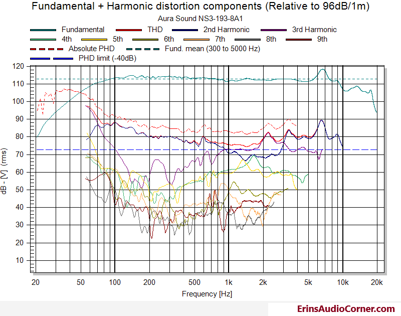
This is the same as above but provides up through 9th order HD. I separated them for legibility.
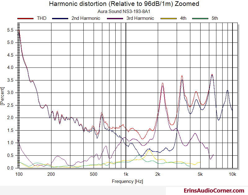
THD Comparison of 90dB/1m vs 96dB/1m:
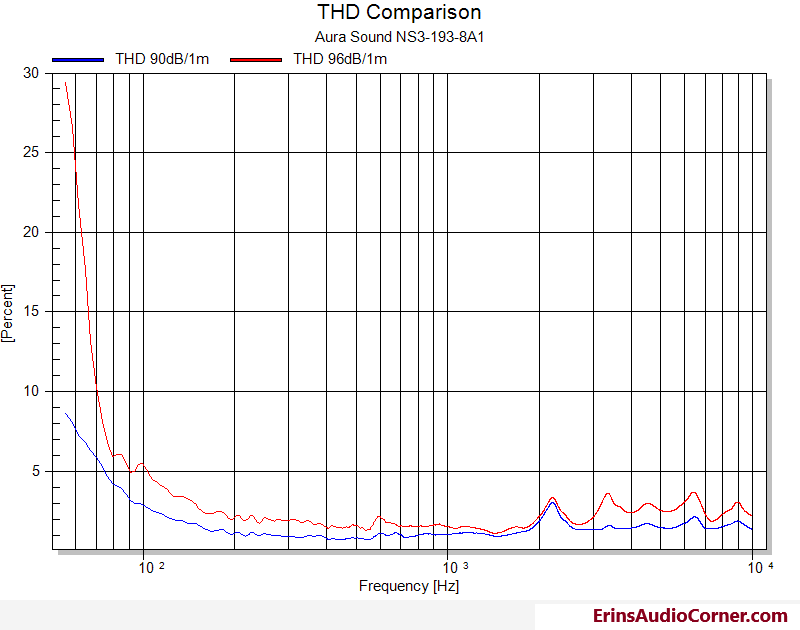
The HD data shows some pretty interesting peaks 600hz, and some others above 2khz with the ~2100hz distortion peaking at just above 3% and comprised of 3rd order. If you multiply 3*2100hz (3 for 3rd order) you get 6300hz; which is really close to the breakup seen in the FR at 6500hz.
Wrap-Up
These are surprising little drive units. Nice linear excursion, nice frequency response on and off-axis. With the fairly linear frequency response they could legitimately be used as a wideband from about 100hz and up.
But… and here comes the but (not the ones Sir Mix-a-Lot likes) … But based on the distortion I couldn’t recommend them for high output volume. And, remember, the measured senstivity is very low; between 75 - 80dB with 2.83v @ 1 meter distance. I could see these being used for systems that don’t need a lot of power (something like a nearfield setup with low background noise) or maybe a little DIY project or just to dip your toes in the water of audio. But, with the low sensitivity and increasing distortion as the volume is raised to typical output levels (mid-80’s to mid-90’s dB levels) they start to show the downside of a small, but linear long throw drive unit. Every application is user dependent so obviously your usage and mileage may therefore vary.
End
If you like what you see here and want to help me keep it going, there’s a Paypal Contribute button at the bottom of each page. Just provide what you can. Every little bit is truly appreciated.
You can also join my Facebook and YouTube pages via the links at the bottom of the page if you’d like to follow along with updates.
Thanks!
